
In procurement reviews, fewer than six technical parameters typically drive 85% of the buy/no‑buy decision for mobile RF antennas; this brief guide extracts those checks so a buyer can validate fit in minutes. The PE51113-2 is named up front to orient readers to the part; this article distills the datasheet and core specs into a rapid checklist and field test plan for US procurement teams.
Why the PE51113-2 Matters for Buyers (Background)
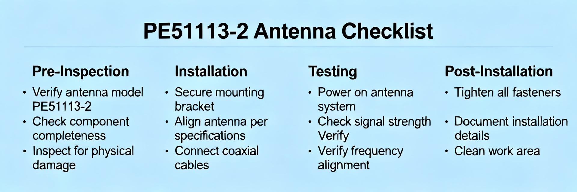
Quick technical snapshot
Point: The part is a compact dual‑band mobile antenna covering common cellular bands with nominal low dBi gain suited for vehicular and base‑station adjuncts. Evidence: Typical units in this category show operation across sub‑GHz and 1–2 GHz ranges and are used for telemetry, fleet voice/data, and backup links. Explanation: Integrators, system designers, and field technicians benefit most—integrators for mounting/connector fit, designers for link budget, technicians for on‑site tuning.
Procurement priorities for this category
Point: Buyers prioritize performance, physical fit, and environmental resilience. Evidence: Procurement surveys rank gain/VSWR, connector type, mounting footprint, and IP/temperature ratings as top concerns. Explanation: The PE51113-2 is commonly considered because it balances electrical specs with a low‑profile mount and standard connector options, reducing surprises at installation and lowering NRE for mounts and cables.
Top Technical Specs from the PE51113-2 Datasheet (Data analysis)
To facilitate rapid cross-referencing during hardware evaluation cycles, the primary parametric thresholds for the PE51113-2 are compiled below:
| Parameter Class | Specification Details | Procurement Verification Check |
|---|---|---|
| Frequency Bands | Sub-GHz (698-960 MHz) & High-Band (1710-2700 MHz) | Ensure matching with carrier band allocations |
| Nominal Gain | Up to 3.5 dBi (Band-dependent peak) | Incorporate 1-2 dB connector loss in link budget |
| VSWR / Impedance | ≤ 2.0:1 / 50 Ω Nominal | Confirm match to transmitter output impedance |
| Connector Options | SMA Male / N-Type (Variant-dependent) | Strictly verify gender configuration before PO |
| Ingress Protection | IP67 Rated (When properly mounted) | Mandatory for outdoor or marine deployments |
Core electrical specs to extract
Point: Capture operating frequency bands, nominal gain (dBi), VSWR/return loss, impedance, and maximum input power. Evidence: These datasheet specs determine link budget and transmitter safety margins. Explanation: For quick comparisons, record: frequency span (MHz), peak and average gain (dBi), VSWR at band centers, 50 Ω impedance, and Pmax (W). These values bridge datasheet numbers to network planning and testing.
Mechanical & environmental specs to verify
Point: Verify connector type/gender, mounting style, dimensions/weight, IP rating, and temperature range. Evidence: Mechanical mismatches (wrong connector gender or mount) are a leading cause of returns, even when electrical specs match. Explanation: Note recommended cable/connector mating and any torque or sealing instructions; a weatherproofing spec or IP66+ and −40°C to +85°C range typically indicate robust field suitability.
Interpreting Performance Charts & Real-world Benchmarks (Data analysis)
Gain, radiation pattern, and VSWR: how to read graphs
Point: Read polar plots, gain vs. frequency, and VSWR curves with test conditions in mind. Evidence: Polar plots show directional lobes and nulls; gain vs. frequency reveals band ripples; VSWR curves indicate match across the band. Explanation: Quick checks: confirm plotted reference plane, note peak vs. average gain, and ensure VSWR stays under 2:1 at operating channels—watch for axes labeled in dBi vs. dBd.
Translating lab numbers to field performance
Point: Lab test conditions (antenna height, cable type/length, absorber environment) shift numbers versus site use. Evidence: Cable losses and mounting proximity to metal can reduce on‑air gain by 1–4 dB. Explanation: Apply practical corrections—expect 0.5–3 dB margin loss for typical vehicular installs, and validate expected VSWR rise from long low‑quality feedlines in acceptance tests.
How to Read the PE51113-2 Datasheet: A Step-by-Step Checklist (Method guide)
Mandatory spec checklist for procurement
Point: Use a prioritized must‑have vs. nice‑to‑have checklist before ordering. Evidence: Focusing on a short list prevents scope creep in RF purchases. Explanation: Must-have: frequency match ± bandwidth, gain ≥ required dBi (specify), VSWR ≤ 2:1, correct connector/gender, mounting compatibility, and power handling ≥ transmitter peak. Nice-to-have: IP66+, wind load data, warranty extension, and factory test report.
- Frequency match: exact channel coverage and tolerance
- Gain: specify min dBi for link budget with margin
- VSWR: target ≤2:1 across critical channels
- Connector & mount: exact mating and physical footprint
- Environment: IP rating and operating temp range
Red flags and ambiguous entries
Point: Watch for missing or vague test conditions. Evidence: Common red flags include unspecified gain reference plane, unclear VSWR test setup, inconsistent units, and unspecified connector gender. Explanation: Follow up with questions: request test reports with setup diagrams, ask for mechanical drawings with tolerances, and demand explicit connector gender and mating part numbers before PO.
Example Integration Scenarios (Case showcase)
Mobile installation example: what to verify
Point: For vehicular installs verify mount type, cable loss, vibration tolerance, and power handling. Evidence: Moving platforms introduce cable flex and vibration that degrade feedline and connector life. Explanation: Map datasheet specs to checks: confirm mount fits vehicle roof or magnetic base, select low‑loss cable with margin in link budget, and ensure antenna Pmax exceeds transmitter peaks plus duty‑cycle considerations.
Fixed-station / rooftop example: what changes
Point: Fixed sites shift priority toward wind load, grounding, and lightning protection. Evidence: Rooftop exposure demands mechanical robustness and bonding points. Explanation: Use datasheet mechanical ratings to verify wind survival, specify grounding and surge protection per site design, and ensure the antenna’s materials and IP rating suit long‑term outdoor exposure.
Quick Buyer Decision Playbook: Ordering, Testing & Next Steps (Action advice)
Pre-order verification steps
Point: Run a short pre‑order runbook to avoid returns. Evidence: Simple checks eliminate the majority of ordering errors. Explanation: Confirm exact part number and variant, verify connector and mounting options, and request factory test reports where critical. For the PE51113-2 specifically, confirm band variant and connector gender before PO to prevent mismates.
Post-delivery validation & acceptance testing
Point: Implement a concise acceptance test plan tied to datasheet numbers. Evidence: A visual inspection plus a two‑point RF check catches most defects. Explanation: Test plan: visual/torque inspection, continuity and connector verification, VSWR sweep with VNA or SWR meter (compare to datasheet thresholds), and a 10–30 minute field smoke test to confirm on‑air performance within expected margins.
Summary
This guide turns a full datasheet into the few checks that decide procurement success: frequency fit, gain, VSWR, connector/mount, and environment. Run the mandatory checklist before ordering and request basic factory test documentation as needed.
- Focus on six parameters—frequency, gain, VSWR, impedance, connector, and environmental rating—to validate the part quickly against system requirements.
- Interpret performance charts by confirming test conditions and applying practical field corrections (expect 0.5–3 dB loss in typical installs).
- Use the pre‑order and post‑delivery playbook: confirm exact part variant and connector, request test reports, and run a VNA or SWR check on receipt.
Frequently Asked Questions
What datasheet specs are most critical for link budget and installation?
The most critical specs are operating frequency range, nominal gain (dBi), VSWR/return loss across your channels, and impedance. Mechanicals—connector type and mounting—are equally critical because a perfect electrical match can be negated by a physical incompatibility.
How should buyers interpret VSWR and gain curves on the datasheet?
Confirm the test reference plane and measurement setup; read gain peaks and average across intended channels and ensure VSWR stays below 2:1 at those frequencies. If the datasheet omits setup details, request the measurement diagram and cable/fixture descriptions.
What immediate steps should procurement take with a new antenna like this?
Before purchase: confirm exact part variant and connector, request factory test reports, and verify lead time and return policy. After delivery: perform visual checks, a continuity/connector inspect, and a VSWR sweep against datasheet thresholds as part of acceptance testing.
How do environmental ratings like IP67 affect installation choice?
High IP ratings (e.g., IP67) enable reliable long-term outdoor or rooftop mounting without requiring extra protective weatherproofing. This reduces overall installation complexity and lower bill-of-materials costs.