
Rated at 1200 V and specified for 50 A nominal collector current, the APT50GH120B packs field-stop IGBT performance into a standard TO-247 package—key parameters that determine its suitability for medium-power inverters and uninterruptible power supply (UPS) topologies. This deep dive translates critical datasheet specifications into practical design guidelines, focusing heavily on Reverse Bias Safe Operating Area (RBSOA), thermal performance, and TO-247 hardware integration for engineering teams validating prototypes.
(1) Device Overview & Application Context
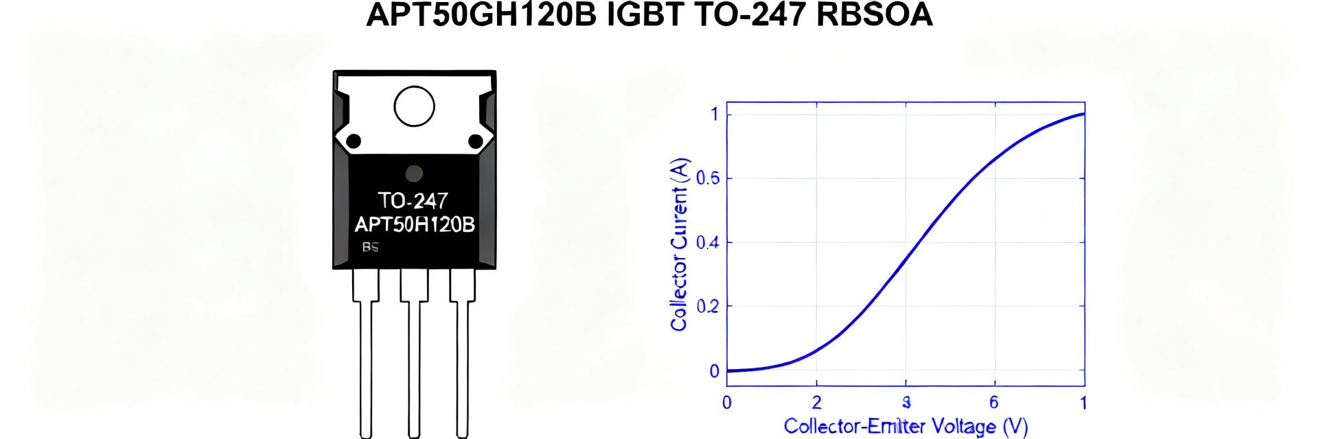
1.1 What APT50GH120B is and where it fits
The APT50GH120B is a high-speed field-stop trench-gate IGBT engineered for high-voltage, medium-power systems. With a 1200 V blocking capacity and a 50 A continuous rating, it balances conduction efficiency with fast switching dynamics. Typical applications include solar inverters, motor control stages, industrial switch-mode power supplies, and welding equipment operating in the 1 to 10 kW range.
| Parameter | Value / Spec |
|---|---|
| Collector-Emitter Voltage (VCES) | 1200 V |
| Nominal Collector Current (IC) | 50 A @ TC = 100°C |
| Typical Saturation Voltage (VCE(sat)) | ~2.0 V @ 25 A (Tj = 25°C) |
| Gate-Emitter Threshold (VGE(th)) | 5.0 V to 6.5 V |
| Thermal Resistance (RthJC) | 0.26 °C/W Maximum |
1.2 How to read the datasheet quickly
When evaluating the APT50GH120B, fast track your design by verifying absolute limits first, then focusing directly on switching loss energies (Eon, Eoff) and gate charge curves. Pay special attention to the normalized transient thermal impedance curve and the RBSOA characteristics, which dictate safety margins under fault conditions and extreme peak switching loads.
(2) RBSOA Explained and Practical Limits
2.1 Interpreting the RBSOA graph for transient and pulsed currents
The Reverse Bias Safe Operating Area (RBSOA) specifies the maximum collector current and collector-emitter voltage limits during the turn-off transient. Unlike the forward-bias SOA, RBSOA is critical when the gate voltage goes low and the inductive load forces current commutation. The boundary curves on the datasheet scale down as pulse duration increases (e.g., from 10 µs to 1 ms). For safe turn-off, your dynamic load line must never cross these boundaries, even momentarily.
2.2 Safe switching practice to avoid RBSOA violations
To prevent localized device failures and dynamic avalanche breakdown during turn-off, follow these implementation rules:
- Control Gate Resistor Value (RG): Tune the turn-off gate resistance to clamp the dynamic dI/dt rate, reducing high voltage spikes.
- Active Snubbers: Implement RC or RCD snubber networks parallel to the collector-emitter path to damp overshoot.
- Active Miller Clamping: Prevent parasite-induced gate turn-on spikes which could drive the device back into a half-on, dangerous state.
(3) Electrical & Thermal Specifications: Design Budgeting
3.1 Key electrical specs to budget for
Conduction and switching losses combine to form the total thermal dissipation requirement. VCE(sat) governs conduction losses, while Eon and Eoff represent the energy lost per switching cycle.
| Loss Type | Formula | Calculated Example (20 kHz, 25 A, Duty = 50%) |
|---|---|---|
| Conduction Loss (Pcond) | P = VCE(sat) * I * Duty | 2.0 V * 25 A * 0.50 = 25.0 Watts |
| Switching Loss (Psw) | P = (Eon + Eoff) * fsw | 0.8 mJ * 20,000 Hz = 16.0 Watts |
| Total Loss (Pdiss) | Pcond + Psw | 41.0 Watts |
3.2 Thermal limits and RthJC/RthCS guidance
To safely dissipate 41 W without thermal runaway, compute the thermal rise from junction to heatsink. Using a RthJC of 0.26 °C/W, the junction-to-case delta is: ΔTj-c = 41 W * 0.26 °C/W = 10.66°C. Add the thermal resistance of your Thermal Interface Material (TIM) and heatsink (RthCS + RthSA) to ensure the peak junction temperature remains below 125°C under maximum worst-case ambient conditions.
(4) TO-247 Package Handling, Mounting & Mechanical Considerations
4.1 TO-247 mechanical outline and mounting best practices
The standard TO-247 package delivers low thermal resistance but requires precise mechanical handling during assembly:
- Mounting Torque: Maintain mounting screw torque strictly within the recommended 0.4 to 0.6 Nm range. Excess torque warps the metal tab, compromising planar contact.
- Lead Bending: Avoid bending leads directly at the plastic body interface; introduce strain relief bends to prevent micro-cracks in the package seal.
- Clamping vs. Screwing: Spring-loaded clips provide more uniform pressure across the package body than center-screw mounting, minimizing contact thermal resistance.
4.2 Thermal interface and PCB considerations for TO-247
When mounting to a heatsink or PCB, apply a thin, high-thermal-conductivity grease or phase-change TIM. In layouts handling high dI/dt paths, position decoupling capacitors as close as possible to the collector and emitter pins to reduce parasitic loop inductance, which contributes directly to peak voltage turn-off spikes.
(5) Prototype Case Study & Validation Checklist
5.1 Short prototype example: 3kW Inverter Stage
A half-bridge inverter operating on a 400 V DC bus uses the APT50GH120B switching at 20 kHz. With peak phase currents at 30 A, turn-off transients generate a peak voltage of 620 V due to stray inductances. Comparing this 620 V / 30 A operating point against the 100 µs RBSOA curve confirms a robust 45% current headroom and 48% voltage margin, verifying safe operation across all dynamic conditions.
5.2 Pre-production test checklist & validation steps
- [ ] Perform double-pulse testing to measure turn-off voltage overshoot at maximum rated currents.
- [ ] Capture real-time dynamic load lines on an oscilloscope to verify zero crossing of the RBSOA boundaries.
- [ ] Monitor case temperatures under steady-state full load using infrared imaging or thermocouple attachment.
- [ ] Validate mechanical strain by subjecting the mounted assembly to 50 thermal shock cycles (-40°C to 125°C).
Summary
- The APT50GH120B is a high-performance 1200V, 50A IGBT optimized for high-power switching topologies.
- Always prioritize dynamic load line validation against the RBSOA curve to safeguard against transient turn-off failures.
- To extract maximum life and reliability, combine precise TO-247 mounting torque with high-performance TIM and conservative thermal budgeting.
Frequently Asked Questions
What are the RBSOA limits for APT50GH120B?
RBSOA limits are given as voltage vs current boundaries for discrete pulse durations on the datasheet. Engineers must compare their worst-case turn-off VCE and instantaneous IC to the curves for 10 µs–1 ms pulses and maintain at least 20-30% margin to avoid secondary breakdown in repetitive operation.
How do I calculate APT50GH120B switching losses at 20 kHz?
Use Pswitch = (Eon+Eoff)*fsw from datasheet Eon/Eoff test points, and add conduction losses Pcond = VCE(sat)*Iavg. Adjust energies for your gate drive and dv/dt conditions; measure with double-pulse test to refine estimates for your layout and gate network.
What is the recommended TO-247 mounting torque for APT50GH120B?
Follow the package mechanical recommendations: use a calibrated torque wrench and the device supplier's suggested torque band (typically 0.4 to 0.6 Nm to ensure contact without cracking). Use insulating hardware when required and thin compliant TIM to minimize RthCS; verify mechanical integrity after thermal cycling.
How do I handle transient thermal impedance for pulsed operations on APT50GH120B?
Utilize the transient thermal impedance ZthJC curve. For brief pulse loads, the effective ZthJC is significantly lower than the steady-state RthJC. Calculate the transient junction temperature rise using delta Tj = Power * ZthJC for the specified duty cycle and pulse width.